Good looking Fog of War
Procedural mesh generation and shaders
2025-02-25
2025-02-25
This is my second blog post about my 3D fog of war implementation. While not strictly necessary, reading the previous blog post will help you understand the context:
Blog Post
Anyway, let's get started!
After all the work to implement my previous solution, I still wasn't completely satisfied with the effect.
Everything worked: it supported multiple units with various lines of sight, it was truly 3D, and it was optimized.
All the boxes were checked!
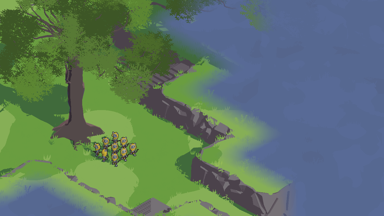
However, every time I asked people to try it, I couldn't help but notice how dark it was.
It's common for RTS games to feature a darker fog of war, and sometimes a dust effect is applied to increase brightness.
But that type of fog just didn't fit the tone of my game. I needed something more cartoonish, so I got back to the drawing board.
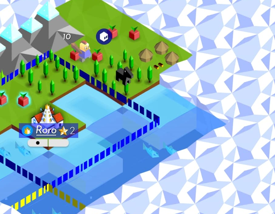
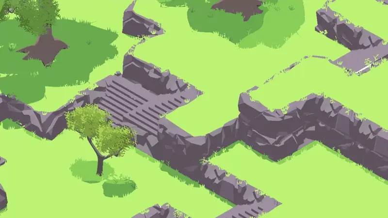
While looking for inspiration, I remembered playing a very cute Turn based Strategy game for mobile called The Battle of Polytopia.
Being tile-based, it featured a fog of war system where each unexplored tile had a "cloud" overlay that hid it completely.
The effect was quite simple, just a sprite for the cell and one for the disappearance effect, but it looked very nice.
So I thought, why not do something similar?
Polytopia had the advantage of being completely 2D, which meant I couldn't just do the same.
I thought about spawning a single mesh for each cell, but since my game is tile-based, that would have
meant either having most sides of the mesh unseen (which would not be good for performance)
or creating a new fog tile for each type of tile in my game (and trust me, there are a lot of tiles).
But then I thought, why not generate it procedurally?
I had never really used Unity's tools to generate meshes before, so this was quite the learning experience.
I won't bore you with all the details of how I got there, as it involved a lot of trial and error, but in the end,
I managed to write a seven-step algorithm that can suit any shape of any type of map:
Every solid tile in the 3D grid is examined alongside its neighboring positions.
Whenever there's no adjacent solid tile, a face is generated. In other words, only the “outer surfaces” are turned into geometry.
This ensures that the final shape corresponds to the exposed boundaries of the solid cells in the grid.
Each face is made by two triangles, whose winding order is determined as to have the normal facing outside.
It also creates a dictionary, mapping each vertex to a list with a single element: the cell that spawned it.
As the faces of each tile are connected, multiple vertices will be created in the same position.
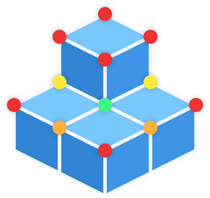
Each created vertex is checked against nearby cells, to determine which parts of the grid it's tied to.
The system uses a small Breadth-First Search (BFS) on the tiles in a 2x2x2 area around each vertex,
from the starting cell we saved earlier, to capture a unique "fingerprint" of grid cells for each vertex.
This data later prevents vertices at the same point in space from being accidentally merged, in case they belong to different parts of the grid.
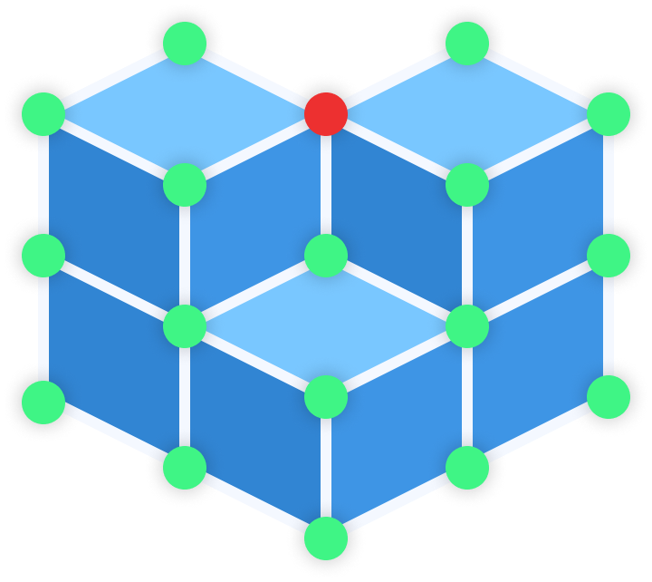
First, the algorithm sorts vertices by their position and connectivity fingerprint.
All vertices sharing the same position and the same set of connected cells are collapsed into one.
Triangles that pointed to the old duplicates are updated to point to the merged vertex, cleaning up the mesh geometry and reducing redundancy.
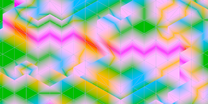
Instead of using typical colors, these "colors" store a small offset vector, which represents the difference between the vertex and inner position it points to.
The inner position is calculated by taking the average of the modes of the centers of each cell from the previous BFS,
separately for each axis.
Red represents X, Green Y, and Blue is Z.
This extra information will become crucial for the shaders, as it indicates where the mesh retracts to, when the tile is explored.
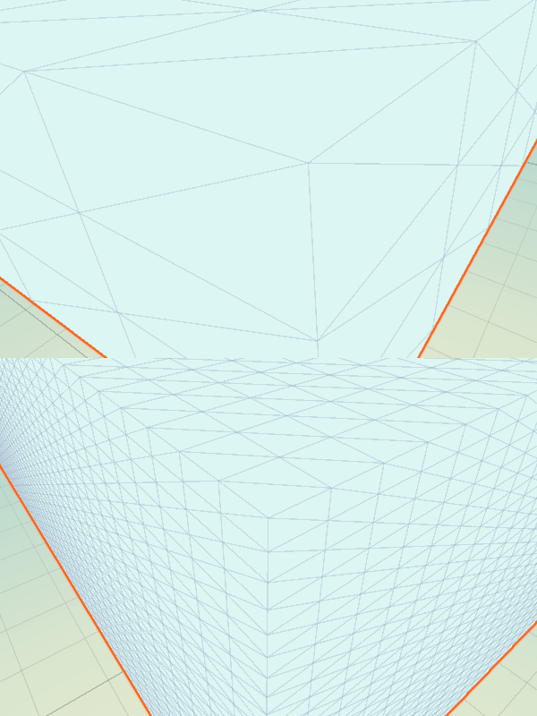
Each triangle is then split into four smaller ones, by calculating the midpoints on each edge.
Normals and color values are blended at the midpoints.
With smaller triangles, the mesh gains enough detail to be smoothed in the next stage.
It will also come in handy for the shaders.
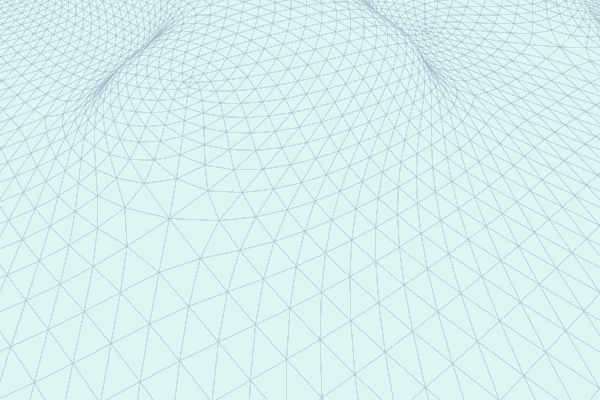
The smoothing process applies a Laplacian smoothing to each vertex, moving it towards the average of its neighboring vertices.
Once the positions are adjusted, the previously stored color offsets are recalculated as to point to the same position as before.
The end result is a softer, more organic-looking geometry.
If the resulting mesh is too large (i.e., has more vertices than allowed), it's split into several smaller sections.
Otherwise, the mesh data (vertices, faces, normals, and vertex colors) is used to generate the mesh.
This step ensures compatibility with Unity's limitation of 65535 vertices with a 16 bit index format.
It also helps with the culling of the parts of the mesh which are not currently on screen.
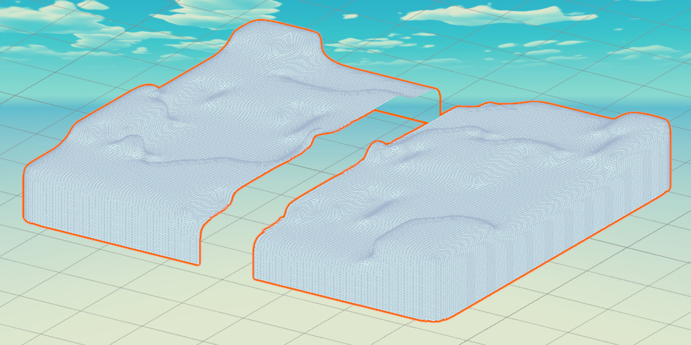
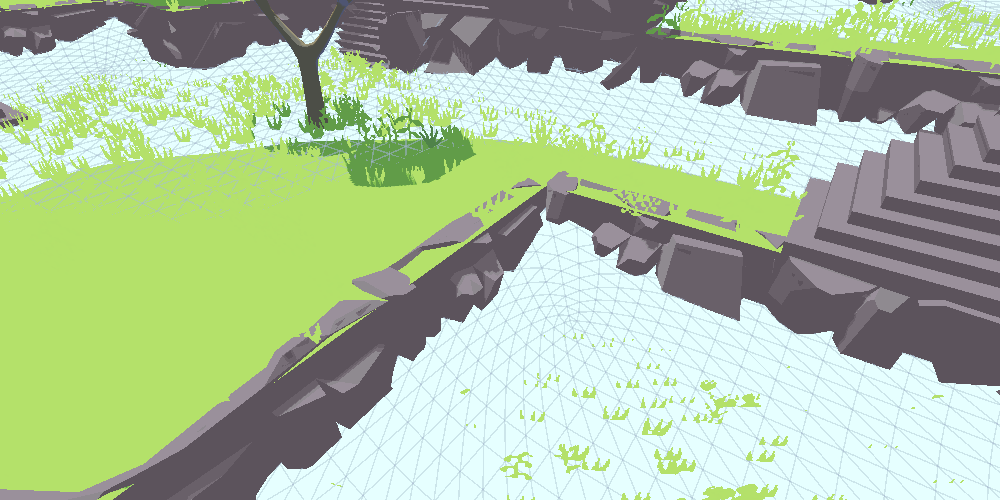
So now I have a mesh, in the shape of the map.
Without any shader applied, the generated mesh will intersect with the ground, being sometimes above and sometimes below.
This is because of the smoothing effect.
What I want to do, is to apply a shader, which uses the vertex colors to interpolate between two positions:
one for when the tile is unexplored, and one for when the tile is unexplored.
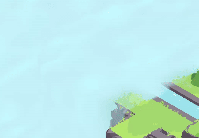
When the tile is unexplored, the mesh will stick out, covering the ground (and the enemy units), making it impossible to see any detail.
Once the tile gets explored, the vertices move underground, hiding from the view of the player. The mesh is still there, but it's not visible anymore.
What I can do now, is read my GPU Buffer, which keeps the data for the current visibility of each tile, to interpolate the position of each vertex.
This way, I can interpolate between the two states smoothly, once the map gets explored.
The intersection between the mesh and the ground is then hidden by a Post Process shader,
which also applies the same colors of the mesh (a white tint) to all the unexplored tiles.
This way, if there is a structure of some kind, or a tree, sticking out from the mesh, it will still be barely visible, and won't ruin the visuals.
There are still a few points I could improve: the post-process shader could have a different pattern, more colors, it could smooth the effect in a different way.
The cloud shader could also change, the wiggle effect is still not perfect, and it can surely be improved.
But overall, I'm almost completely satisfied with it!
If I make more big changes, I will make sure to write another blog post, so stay tuned!
If you liked the post, don't forget to follow me on X or Twitch! You can find all of my links in my Home Page